Home
› Logic Diagram And Truth Table Of Jk : Solved The 74ls112 J K Flip Flop Detailed In Fig 7 16 Uses Chegg Com - Truth table is the basic representation of the inputs vs the outputs for any logic design or circuit.
Logic Diagram And Truth Table Of Jk : Solved The 74ls112 J K Flip Flop Detailed In Fig 7 16 Uses Chegg Com - Truth table is the basic representation of the inputs vs the outputs for any logic design or circuit.
Logic Diagram And Truth Table Of Jk : Solved The 74ls112 J K Flip Flop Detailed In Fig 7 16 Uses Chegg Com - Truth table is the basic representation of the inputs vs the outputs for any logic design or circuit.. Truth table shows the corresponding outputs for every combination of inputs. It is used to find out if a propositional expression is true for all legitimate input values. The logic diagram consists of gates and symbols that can directly replace an expression in boolean arithmetic. Representing data as binary values means. You can enter logical operators in several different formats.
The truth tables for the flip flop conversion are given below. Give the logic circuit diagram and complete true table of : Draw the truth table for a logic function that takes a three bit binary number and produced an output that is 0 for even parity and 1 for odd parity. The user inputs the output values in the x column it will be a chart much like this Truth tables offer a simple and easy to understand tool that can be used to determine the output of any logic gate or circuit for all input combinations.
Flip Flops In Electronics T Flip Flop Sr Flip Flop Jk Flip Flop D Flip Flop Circuits from www.circuitstoday.com Truth table shows the corresponding outputs for every combination of inputs. The jk flip flop is basically a gated rs flip flop with the addition of the clock input circuitry. The logic diagram consists of gates and symbols that can directly replace an expression in boolean arithmetic. The logic circuit for jk flip flop constructed using sr flip flop constructed from nor latch is as shown below Does my truth table correct? A.) f=x' y+y z' (x y z) b.) g=a c+ b' c+ a' b. By using this gate, we can implement nor and nand gates. Logic diagrams are diagrams in the field of logic, used for representation and to carry out certain types of reasoning.
Consider the truth table of jk flip flop below.
These values will be like a standard truth table (in order by binary counting) ex/ and logic: Below is the circuit diagram of a jk flip flop, consisting of 4 nands. A = 0, b = 1, c = 1. Does my truth table correct? A, b and cin, which add three input binary digits and generate two binary outputs i.e. It is used to find out if a propositional expression is true for all legitimate input values. The rows of a basic truth table contain the boolean logic true or false values, while the columns list the premises of a scenario as well as the conclusion. A logic gate is a device that can perform one or all of the boolean logic when combined, several gates can make a complex logical evaluation system that has many inputs and outputs. We will only focus on the first two nands: The s and r inputs of the rs bistable have been replaced by the two inputs called. Computers are based on electrical circuits where we can detect whether current is flowing or not. Jk flip flop construction, logic circuit diagram, logic symbol, truth table, characteristic equation & excitation table are discussed. You can enter logical operators in several different formats.
You can see in the circuit diagram the inputs are connected to the outputs or it takes the output. This video explains how to combine logic functions to form more complex, combined logic functions. Use the buttons below (or your keyboard) to enter a proposition. Featuring a purple munster and a duck, and optionally showing intermediate results, it is one of the better instances of its kind. The jk flip flop is basically a gated rs flip flop with the addition of the clock input circuitry.
Jk Flip Flop Using Nand Gate Truth Table Excitation Table Characteristic Table Youtube from i.ytimg.com You can see in the circuit diagram the inputs are connected to the outputs or it takes the output. Consider the truth table of jk flip flop below. It is used to find out if a propositional expression is true for all legitimate input values. These values will be like a standard truth table (in order by binary counting) ex/ and logic: We will discuss each herein and demonstrate ways to convert between them. The ic power source vdd ranges from 0 to +7v and the data is available in the datasheet. Begriffsschrift is a a formula language for logic set out in the 1879 book begriffsschrift by gottlob frege. The truth tables for the flip flop conversion are given below.
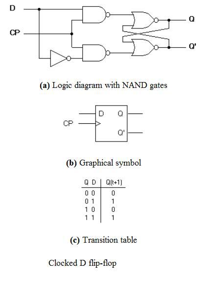
The logic diagram consists of gates and symbols that can directly replace an expression in boolean arithmetic.
The ic power source vdd ranges from 0 to +7v and the data is available in the datasheet. Binary uses base 2, so we have just two possible values 1 or 0. The symbol and truth table of a not gate with one input is shown below. Truth table is the basic representation of the inputs vs the outputs for any logic design or circuit. Consider the truth table of jk flip flop below. Truth tables, logic, and demorgan's laws. At the most elementary level, an elecrtonic device can only recognise the presence or absence of current or voltage. Truth tables summarize how we combine two logical conditions based on and, or, and not. Master slave flip flop circuit electronic circuits and diagrams. The logic circuit for jk flip flop constructed using sr flip flop constructed from nor latch is as shown below These values will be like a standard truth table (in order by binary counting) ex/ and logic: This tool generates truth tables for propositional logic formulas. A venn diagram is, in essence, a visual truth table.
Featuring a purple munster and a duck, and optionally showing intermediate results, it is one of the better instances of its kind. A.) f=x' y+y z' (x y z) b.) g=a c+ b' c+ a' b. Solved the 74ls112 j k flip flop detailed in fig 7 16 c3f8a logic diagram for t flip flop digital resources. This tool generates truth tables for propositional logic formulas. When a logic gate has only two inputs, or the logic circuit to be analyzed has only one or two gates, it is fairly easy to remember how a.
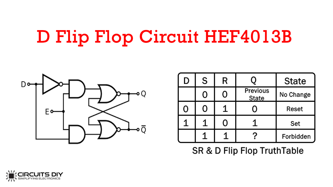
D Flip Flop Circuit Using Hef4013b Truth Table from circuits-diy.com The jk flip flop is basically a gated rs flip flop with the addition of the clock input circuitry. Logic tells us that if two things must be true in order to proceed them both condition_1 and condition_2 must be true. This tool generates truth tables for propositional logic formulas. Binary uses base 2, so we have just two possible values 1 or 0. A truth table is a device for using this form syntax in calculating the truth value of a larger formula given an interpretation (an assignment of truth values to sentence letters). It is used to find out if a propositional expression is true for all legitimate input values. Because q and q are always different, we can use the. 4 logic s and truth table 1.
Truth tables offer a simple and easy to understand tool that can be used to determine the output of any logic gate or circuit for all input combinations.
Binary uses base 2, so we have just two possible values 1 or 0. A, b and cin, which add three input binary digits and generate two binary outputs i.e. By using this gate, we can implement nor and nand gates. Featuring a purple munster and a duck, and optionally showing intermediate results, it is one of the better instances of its kind. Use the buttons below (or your keyboard) to enter a proposition. You can enter logical operators in several different formats. An adder is a digital logic circuit in electronics that performs the operation of additions of two number. A logic gate is a device that can perform one or all of the boolean logic when combined, several gates can make a complex logical evaluation system that has many inputs and outputs. Logic diagrams are diagrams in the field of logic, used for representation and to carry out certain types of reasoning. 4 logic s and truth table 1. The truth tables for the flip flop conversion are given below. The ic power source vdd ranges from 0 to +7v and the data is available in the datasheet. Consider the truth table of jk flip flop below.